
Download ConceptBase Φ
Books&Manuals Φ
ConceptBase Team Φ
Home
Model-Based Cybersecurity Analysis: Extending
Enterprise Modeling to Critical Infrastructure
Cybersecurity
A Tutorial at EDOC 2026, 2026-09-16
Master solution for the exercise: see end of page
Long term archive: zenodo.org/records/22938763
Manfred Jeusfeld, University of Skövde, Sweden (manfred.jeusfeld@acm.org)
The source models (*.sml, *.sml.txt,*.cbs) in this directory (incl. subdirectories) and their derivates (*.gel,*.png, *.svg) are provided under a
CC BY-NC 4.0 license:
Attribution-NonCommercial 4.0 International.
A1. Install ConceptBase
Install ConceptBase via the "Download ConceptBase"
link for Linux, Windows, and MacOS. You need Java 11 or higher to do so.
You can configure your ConceptBase
installation to directly start the example
graph files (*.gel). The graph files contain all necessary Telos definitions including the
DeepTelos axioms and the dedicated graphical types. You only need to configure your web browser
to open the CBGraph utility when you click a graph file. The procedure is simple:
- Use your Web browser (e.g. Firefox) to click on a link to a graph file like
acrosslevels.gel (a sample ConceptBase graph file).
The browser shall ask you whether to download the file or associate an application. Choose to associate an application.
Then, browse to the installation directory of ConceptBase.cc (Windows: c:\conceptbase, other: $HOME/conceptbase).
Type for Windows "cbgraph.bat" and for other platforms "cbgraph" in the filename field and press OK.
Afterwards, a click on a link to a graph file shall directly start CBGraph. Our web servers of ConceptBase use as Mime type for graph files application/cbgraphfile or application/x-cbgraphfile. The latter is preferred.
The main user interfaces of ConceptBase are CBIva (textual Telos editor plus interface to define and run queries), and CBGraph (graph editor for
Telos models. You can start CBIva from CBGraph by "File / Start CBIva Workbench". You can also right clich on an element in CBGraph and select
"Display in Telos Editor" to see just the definition of this element.
A2. Browse sources and examples
The Telos sources for the tutorial are provided as text files *.sml.txt ("Telos files").
In addition, you find self-contained ConceptBase
graph files, ready to be started from your web browser after installation of ConceptBase.
- Sources of the Elvira Taxonomy as well as examples cyber-physical models.
- Graph files for the tutorial.
- Queries to analyze cyber-physical models.
1. Introduction to the tutorial
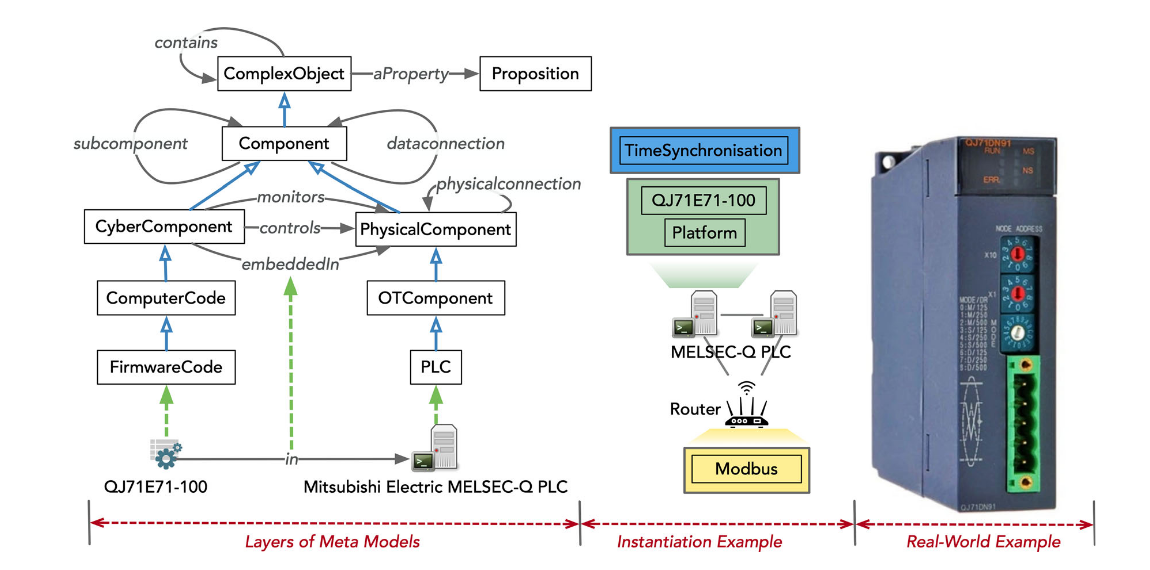
This tutorial shows how to use a taxonomy of cyber-physical components to model comprehensive
enterprise models, in particular for the power grid sector. The tutorial is based on the results
of the EU Elvira project at the University of Skövde. Specifically, we use the method as described in the paper:
Yuning Jiang, Manfred A. Jeusfeld, Jianguo Ding, Elin Sandahl:
Model-Based Cybersecurity Analysis:
Extending Enterprise Modeling to Critical Infrastructure Cybersecurity. Bus. Inf. Syst. Eng. 65(6): 643-676 (2023)
The tutorial shall introduce into a taxonomy-based modeling of enterprise networks in the area of
critical infrastructures. The taxonomy covers physical assets, control hardware, network
components, software components and communication channels between software components. We
discuss how the integrated part models are used to measure the criticality of software components to
cyber attacks. An example from the power grid domain shows the functions of an implementation.
2. The Elvira Taxonomy
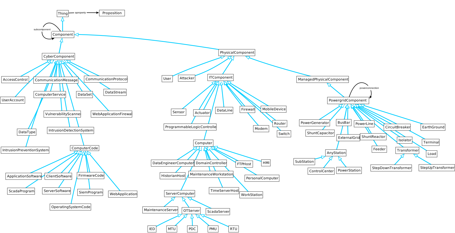
The Elvira Taxonomy is the basis for creating cyber-physical models.
It comprises of cyber components (software files, databases, data streams, ..)
and physical components (computers, power grid components such as transformers, network devices such as routers,
physical connections such as data lines, power lines) and so forth.
A cricial relation is "subcomponent". For example, computer is regarded as the container of software components.
Networks are regarded as containers of the respective IT components, substations are regarded as containers
of power grid components.
3. The NineBus Reference Model
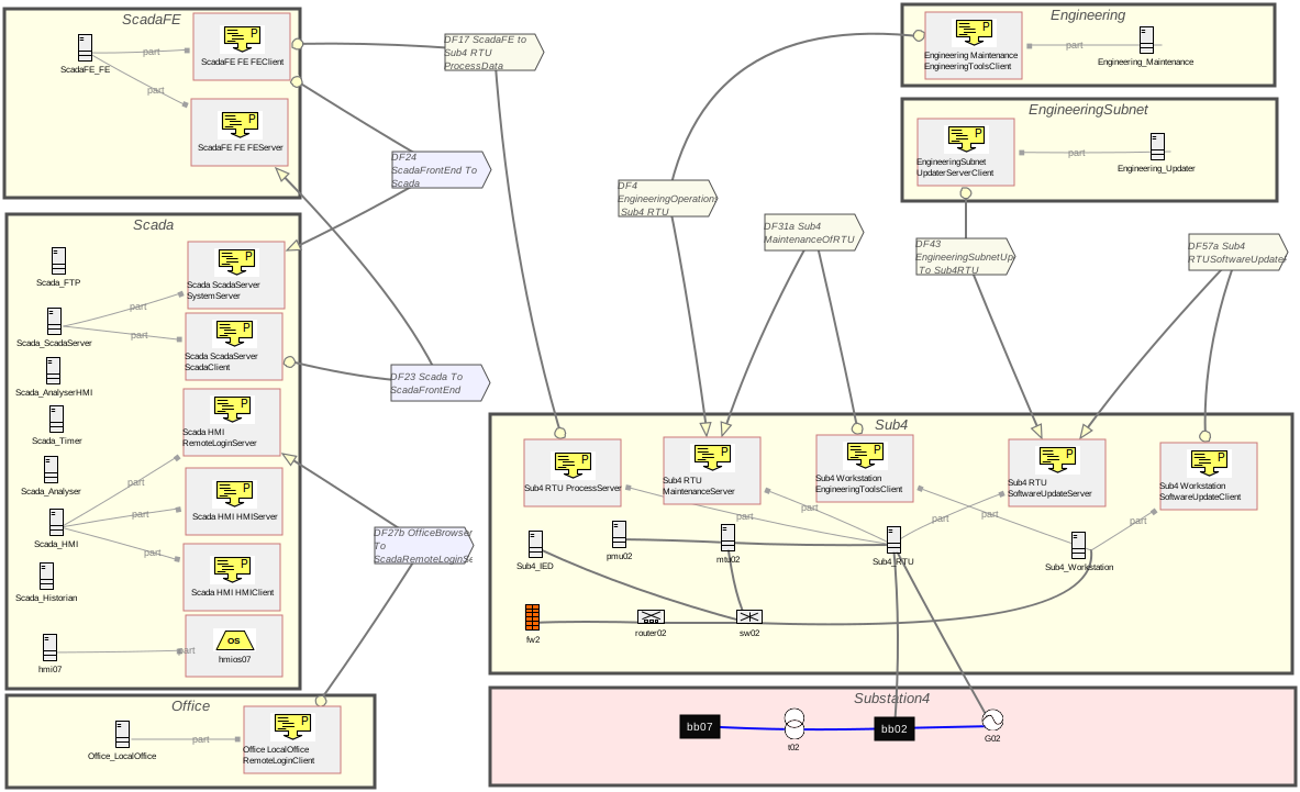
The reference model follows the IEEE NineBus substation model but adds the IT components, the networks and the software components typically
used by power grid companies. From this reference model, simulation models for power flow simulation (PyPower) and for attack simulation (SecuriCAD)
were extracted in the ELVIRA project, but not shown in this tutorial. There are two layers of the reference model: the topology of the NineBus
reference model is in the module "NineBusSC". The properties of the components, e.g. the electrical properties of a transformer are in the
sub-module "nbconfsc1". Here is an example of such properties:
t02 in StepUpTransformer with
   aproperty
    vendor : "TRAFCOM SE"; maxpower : "30000000";
    hv_bus : "bb07"; lv_bus : "bb02";
    sn_kva : "192000.0"; vn_hv_kv : "230.0";
    vn_lv_kv : "18.0"; vsc_percent : "11.2";
    vscr_percent : "0.3"; pfe_kw : "29.0";
    i0_percent : "0.071"; shift_degree : "0";
    tp_phase_shifter : "FALSE"; parallel : "1";
    df : "1.0"; in_service : "TRUE"
end

hmios07 in OperatingSystemCode with
   aproperty
    vendor : "Canonical"; model : "Ubuntu"; version : "18.04.2 LTS"
end
4. Adding new concepts to the taxonomy
Let's assume that we want to add a new component type for wireless access points to the taxonomy. Here is what it may look like
WirelessAccessPoint in ComponentType isA ITComponent with
  comment
    definition:"A wireless access point (WAP), also called just access point (AP), is a networking device
    that allows other Wi-Fi devices to connect to a wired network or wireless network (source: Wikipedia)".
end
The new component type is defined as subclass of ITComponent. You may want to have an intermediate component type "NetworkComponent" to distinguish
such devices from computers and the like:
NetworkComponent in ComponentType isA ITComponent end

WirelessAccessPoint in ComponentType isA NetworkComponent with
  comment
    definition:"A wireless access point (WAP), ....
end
The comment may be used for textual definitions. It is not mandatory.
The taxonomy allows to assign graphical types to any object, e.g.
ROUTER_GT in Class,JavaGraphicalType with
   property
    linecolor : "0,0,0"; fontsize : "8";
    image : "powergrid/router.png"; linewidth : "1"; textcolor : "10,10,10";
    size : "resizable"
  implementedBy implBy : "i5.cb.graph.cbeditor.CBIndividual"
  priority pr : 40
  rule gtrule : $ forall x/Router (x graphtype ROUTER_GT) $
end
The rule assigns a the graphical type to instances of the component type "Router".
5. Analyze cyber-physical models by queries
In this tutorial, the purpose of queries is to find flaws and incomplete definitions in cyber-physical models.
Let's assume we want to find out whether powergrid components are connected to a busbar. The first attempt is
a query like:
ConnectedToBusBar in QueryClass isA PowergridComponent with
  constraint c1: $ exists b/BusBar (this powerconnection b) $
end
A more useful version is to negate the membership constraint:
NotConnectedToBusBar in QueryClass isA PowergridComponent with
  constraint c1: $ not exists b/BusBar (this powerconnection b) $
end
It returns those powergrid components that are not connected to a busbar. Technically, busbar themselves are not connected to a busbar.
We may want to exclude them:
NotConnectedToBusBar in QueryClass isA PowergridComponent with
  constraint c1: $ not (this in BusBar) and not exists b/BusBar (this powerconnection b) $
end
Other more demanding queries could be
- Find all IT components whose programs are communicating with the main SCADA software in the control center.
- Find software components that control a given actuator.
- Check whether a logical data flow between to software programs is supported by the topology of the network.
- Which firewalls govern the traffic between two given IT components?
6. Example: The cyber-physical model for a small municipal powergrid
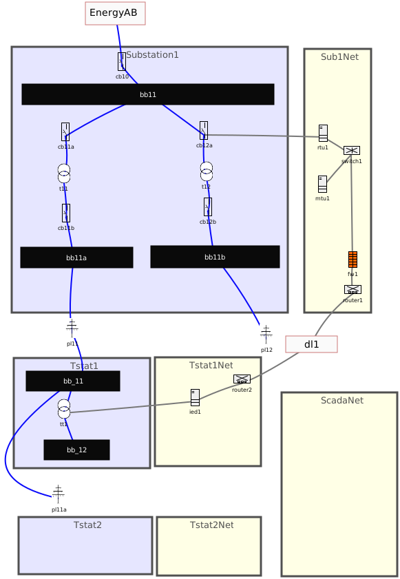
The (rather incomplete) small powergrid model below is from a typical municipal powergrid company.
They use a substation to get electricity from a national powergrid company Energy AB.
After transforming the voltage down, it is passed to smaller substations such as "Tstat1". Those transformer stations are serving approximately a hundred households. To do so, the voltage has to be further transformed down to 400V.
The yellow sectors are the networks for the substation and the transformer station(s). Typical components are routers, switches and
firewalls. RTUs (remote terminal units can control/monitor powergrid components.
The transformer stations may have a simpler setup, Here, it just uses and intelligent electronic device to control the transformer.
Power lines are connecting remote powergrid components. Data lines connect remote IT components (here, two routers).
7. Practical exercise 1: Extend and analyze the municipal powergrid model
Here are some tasks to extend and analyze the municipal powergrid model. The completion may take 60-90 minutes.
You do not need to solve all tasks!
Extending the model
Load the Elvira smallgrid model into CBGraph and extend it as follows:
- Add powergrid elements to Tstat2 analogous to the elements in Tstat1. Link the incoming busbar of
Tstat2 to powerline p11a.
- Add a network Tstat2Net analogous to Tstat1Net.
- Create data connections between rtu1 and the transformer t12 in Substation1. Create a 2nd RTU rtu2 that controls the left side of
the substation similar to rtu1.
- Define a Scada network with a computer "scada_server" running a ScadaProgram called "microscada1". Add the usual network components like router, switch and firewall to the the Scada network. Link the router of the Scada network to the router in Sub1Net via a dataline (taxonomy concept DataLine). Add a "processserver67" (taxonomy type FirmwareCode) as sub-component to mtu1.
- Create a data stream (taxonomy UnidirectionalDataSteam) between "microscada1" (sender) and "processserver67".
Hint: You can right-click on the element "bb_11" of Tstat1 and select "Display in Telos Editor" to see its definition. It will display:
bb_11 in BusBar with
   powerconnection
    pc1 : pl11; pc2 : pl11a
end
Rename the elements to fit Tstat2 and then press the "Tell" button of the Telos Editor to define it.
You can add an element from the TelosEditor to the diagram by double-clicking it in the TelosEditor, then right click it and select "Display in GraphEditor".
Use Elvira reference model as a role model if you are unsure about how to model
certain elements.
The diagram elvira-smallgrid.gel can be saved by the "-> GEL" button of the graph editor CBGraph.
Analyzing the model
Here are some tasks to pinpoint errors or incompleteness in the model:
- Define a query that returns those (power grid) components of a substation that have no data connection to an OT server (RTU, IED, ...)
- Check whether a logical data flow between to software programs is supported by the topology of the network. In particular,
whenever there is a data stream between two software components, then there must be a path of data connections between the
IT/OT components on which the software components run.
Target solution
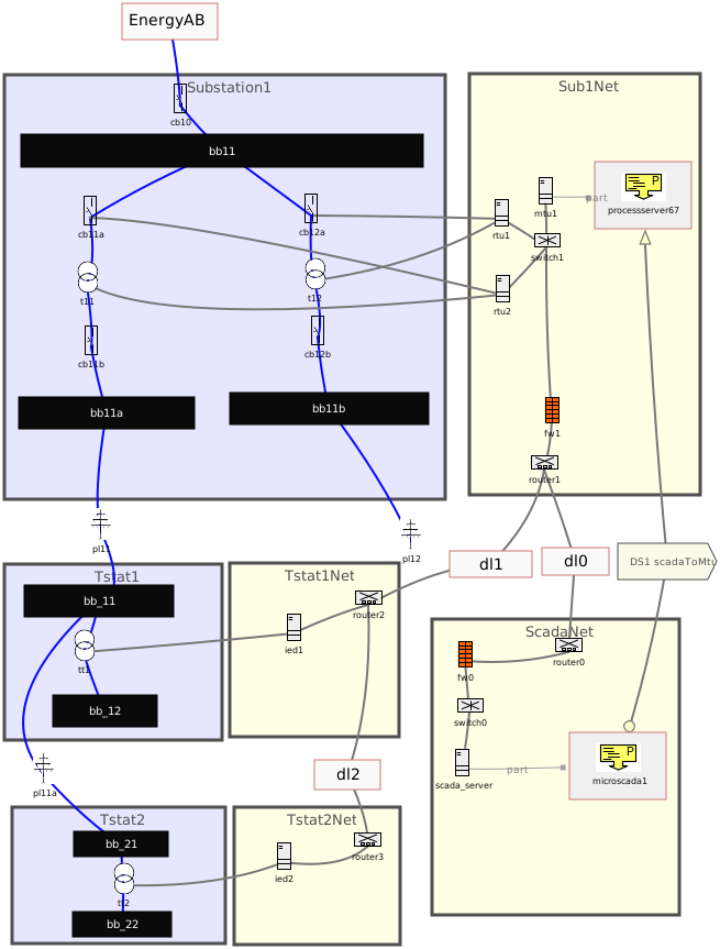
Master solution
Send me an email to receive the master solution for above exercise: manfred.jeusfeld@acm.org
8. Practical exercise 2: Complete the data streams to OT servers
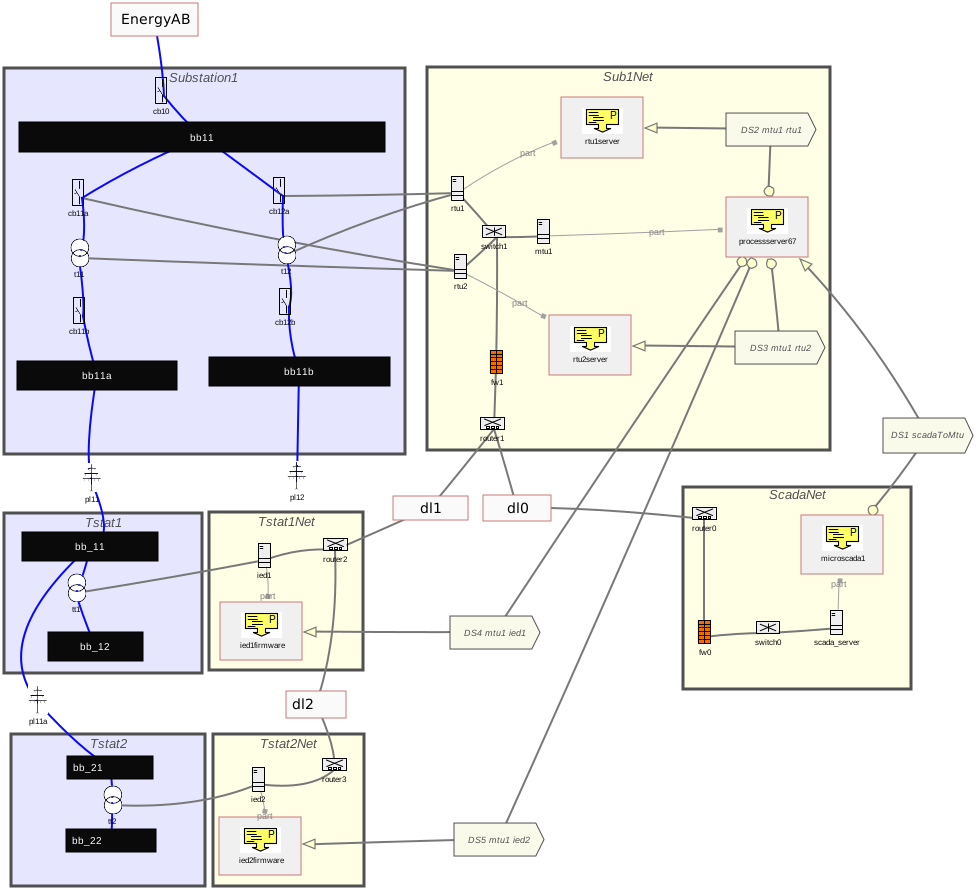
The previous practical execise only had one data stream beween the SCADA computer and the MTU of Sub1Net. Here are additional
tasks.
- Add data streams from the software of "processserver67" running on "mtu1" and the software on "rtu1", "rtu2", "ied1" and
"ied2".
The figure below is for inspiration. You may deviate from it.
- Add two more networks. The DMZ" network shall include at least two computers. One for the historian server,
a second for a remote login server (compare "Scada_HMI" in the NinceBus reference model. The "Office" network shall contains
a number of office PCs that have clients software to remotely login to "Scada_HMI". Add data streams between the new software
components analogous to the reference model.
- Define a query that returns all software components that can directly or indirectly indluence a powergrid component.
Software running on an OT component (instance of "OTserver") that has a data connection to a power grid component is assumed to
directly influence it. A software components that has a data stream to such a direct influencing software is assumed to
indirectly influence the power grid component. There may be chains of such data streams.
© Manfred Jeusfeld, 2026-08-17 (2026-10-15)